User Tools
Sidebar
products:sbc:edge2:hardware:start
Table of Contents
Edge2 Hardware Documentation
Edge2 Interfaces
Top side
| Component | Purpose | |
|---|---|---|
| 1 | USB-A | USB 3.1, blue colour |
| 2 | USB-C | USB 3.1 & Display Port |
| 3 | HDMI | Type-A Female, up to 8K@60Hz, HDCP 2.3 |
| 4 | USB-C | Only for power delivery |
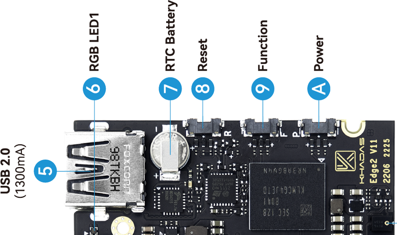
| 5 | USB-A | USB 2.0, black colour |
| 6 | RGB LED1 | Status indicator LED |
| 7 | RTC Battery | RTC battery for the real time clock |
| 8 | Reset Button | Force reboot your Edge2 |
| 9 | Function Button | Press this 3 times in 2 seconds to enter MaskROM mode |
| A | Power Button | This button turns on your Edge2 |
| B | Digital Microphone | Right digital microphone |
| C | Camera3 | 30-pin, 0.5mm pitch, 4-lane, dual cameras, 16MP 30FPS image signal processing |
| D | Camera2 | 30-pin, 0.5mm pitch, 4-lane, dual cameras, 16MP 30FPS image signal processing |
| E | Camera1 | 30-pin, 0.5mm pitch, 4-lane, dual cameras, 16MP 30FPS image signal processing |
| F | Digital Microphone | Left digital microphone |
| G | G-Sensor | 3-axis accelerometer |
| H | MHF4 Antenna | Wi-Fi and Bluetooth antenna connector |
| I | SPI Flash | Flash memory module that interfaces over SPI |
| J | PWM Fan Header | 4-wire fan header utilising pulse width modulation |
| K | RGB LED2 | Status indicator LED |
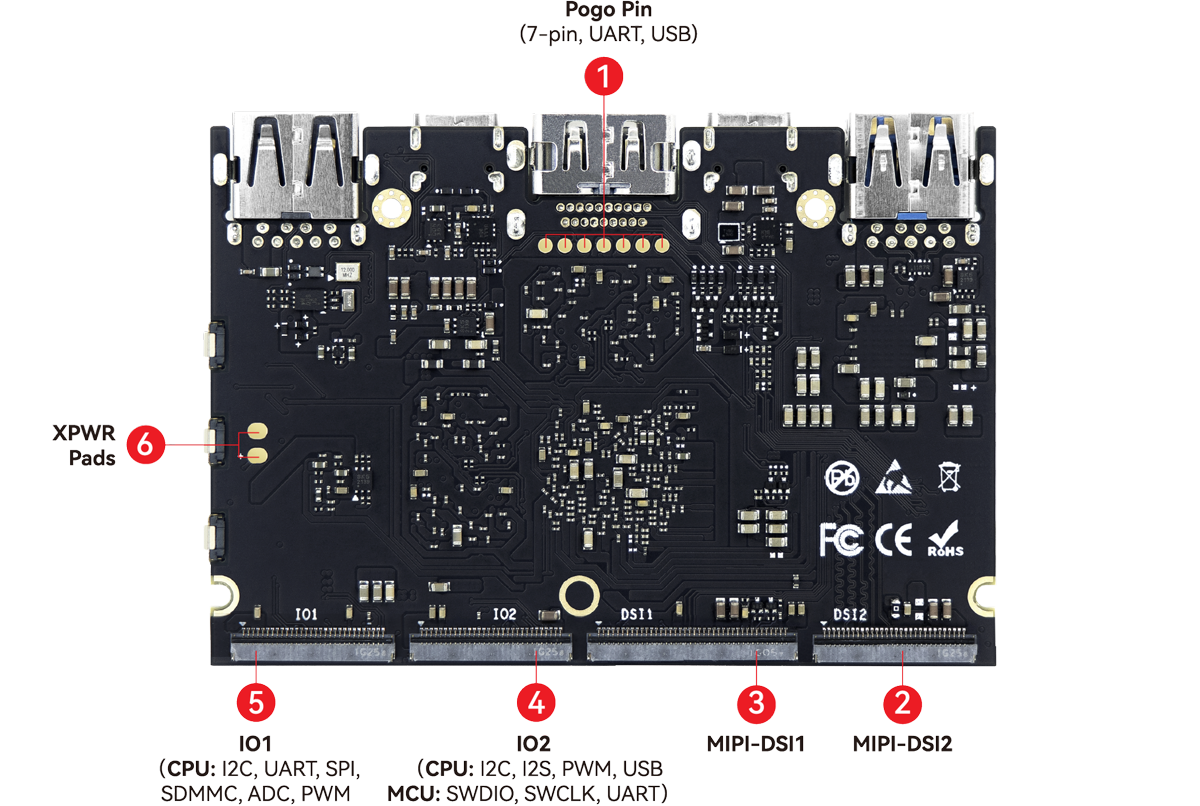
Back side
| Component | Purpose | |
|---|---|---|
| 1 | Pogo pins | Debug and USB hub pads |
| 2 | DSI2 | 30-pin, 0.5mm pitch, provided data path for dual |
| 3 | DSI1 | 40-pin, 0.5mm pitch FPC connector for 4-lane 1080P displays && TP touch input |
| 4 | IO2 | 30-pin, 0.5mm pitch,connect the expansion board |
| 5 | IO1 | 30-pin, 0.5mm pitch, connect the expansion board |
| 6 | XPWR pads | Extennal POWER key pads |
Hardware buttons
| Reset | Function | Power | Purpose |
|---|---|---|---|
| x | Force Reboot Edge2 | ||
| x | Enter Upgrade Mode (TST) | ||
| x | Power On/Wake Up Edge2 | ||
| x | x | Enter Upgrade Mode (KEYS) |
Special button shortcuts
- Press
FUNCTION3 times in 2 seconds to enterMaskROMmode - Other OOWOW button shortcuts
GPIO header
2022/07/15 23:37
· 2 Comments
Schematics & Drawings
Datasheets
Misc
Last modified: 2025/12/04 02:41 (external edit)


