User Tools
Sidebar
products:sbc:vim2:hardware:start
Table of Contents
VIM2 Hardware Documentation
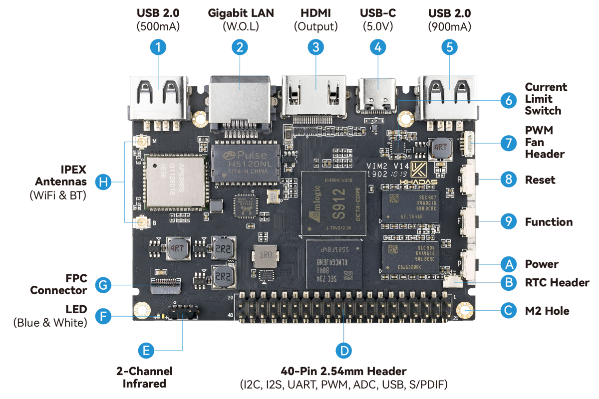
VIM2 Interfaces
Top side
| Component | Purpose | |
|---|---|---|
| 1 | USB-A | USB 2.0 speed, 500mA max output |
| 2 | RJ-45 | Gigabit Ethernet with Wake-On-LAN (WOL) |
| 3 | HDMI | HDMI 2.0a output with CEC, 4K@60Hz |
| 4 | USB-C | USB 2.0 OTG and 5V power input, can be used for upgrading the OS |
| 5 | USB-A | USB 2.0 speed, 900mA max output |
| 6 | Current Limit Switch | Prevents damage to VIM2 during uneven loading conditions |
| 7 | Fan Header | 4-wire fan header utilising pulse width modulation |
| 8 | Reset Button | Force reboot your VIM2 |
| 9 | Function Button | Press this 3 times in 2 seconds to enter MaskROM mode |
| A | Power Button | This button turns on your VIM2 |
| B | RTC Battery Header | Header for attaching a battery for the real time clock |
| C | M2x4 Mounting Point | For mounting to cases and heatsinks |
| D | 40-Pin GPIO | Learn how to access the GPIO from here, or use it to add a Toneboard |
| E | Infrared Module | 2-channel infrared receiver for use with Khadas IR remote |
| F | LEDs | Status indicator LEDs |
| G | FPC Connector | 10-pins, 0.5mm pitch, with I2C, IOs |
| H | I-Pex Wi-Fi / Bluetooth Connector | Wi-Fi / BT Antenna connector |
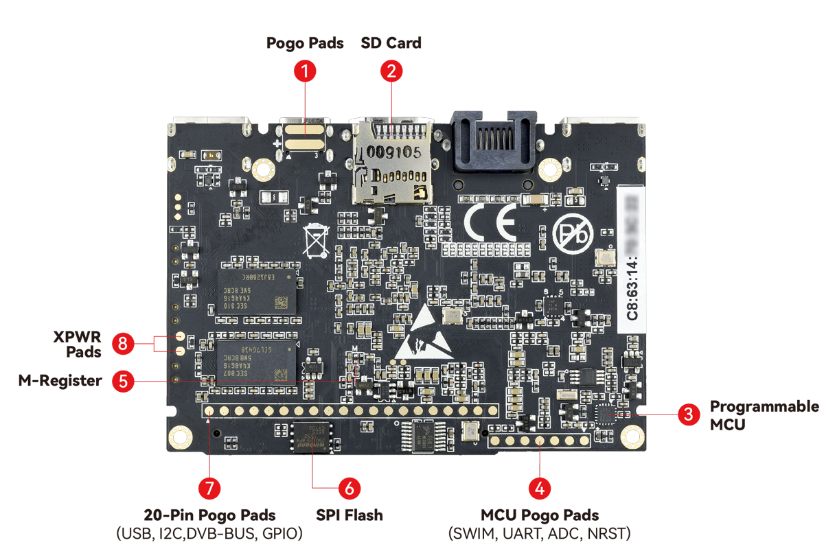
Back side
| Component | Purpose | |
|---|---|---|
| 1 | Pogo Pads | External 5V power input, can be provided by vTV Board(DVB Tuner) |
| 2 | Micro-SD Card Slot | Boot alternative OSes via a micro-SD card, or just for extra storage |
| 3 | MCU | STM8S003 micro-controller with programmable EEPROM |
| 4 | MCU Pogo Pads | SWIM, UART, ADC, NRST |
| 5 | M-Register | Shortcut to mask the eMMC |
| 6 | SPI Flash | Flash memory module that interfaces over SPI |
| 7 | 20-Pin Pogo Pads | USB, I2C, DVB-Bus, IOs, for docking with the vTV Board(DVB Tuner) |
| 8 | XPWR Pads | Connect an external power switch using these pads |
Hardware buttons
| Reset | Function | Power | Purpose |
|---|---|---|---|
| x | Force Reboot VIM2 | ||
| x | Enter Upgrade Mode (TST) (V14 only) | ||
| x | Power On/Wake Up VIM2 | ||
| x | x | Enter Upgrade Mode (KEYS) |
Special button shortcuts
- Press
FUNCTION3 times in 2 seconds to enter MaskROM mode. (V14 only)
GPIO header pinout
| SIGNAL | PIN | PIN | SIGNAL |
|---|---|---|---|
| 5V | 1 | 21 | GND |
| 5V | 2 | 22 | I2C_SCK_A |
| HUB_DM1 | 3 | 23 | I2C_SDA_A |
| HUB_DP1 | 4 | 24 | GND |
| GND | 5 | 25 | I2C_SCK_B |
| GPIODV_21 | 6 | 26 | I2C_SDA_B |
| GPIODV_22 | 7 | 27 | 3.3V |
| GPIODV_23 | 8 | 28 | GND |
| GND | 9 | 29 | I2S_SCLK |
| ADC_CH0 | 10 | 30 | I2S_MCLK |
| 1.8V | 11 | 31 | I2S_SDO |
| ADC_CH2 | 12 | 32 | I2S_LRCK |
| SPDIF | 13 | 33 | I2S_SDI |
| GND | 14 | 34 | GND |
| UART_RX_AO_B | 15 | 35 | PWM_D |
| UART_TX_AO_B | 16 | 36 | RTC_CLK |
| GND | 17 | 37 | GPIOH_5 |
| Linux_RX | 18 | 38 | EXP_INT |
| Linux_TX | 19 | 39 | GPIODV_13 |
| 3.3V | 20 | 40 | GND |
2022/07/08 03:32
· 1 Comment
Schematics & Drawings
Datasheets
Misc
Last modified: 2025/12/04 02:38 (external edit)


