User Tools
Sidebar
products:sbc:edge1:hardware:interfaces
Table of Contents
Edge1 Interfaces
Top Side
| Component | Purpose | |
|---|---|---|
| 1 | USB-A | USB 3.0, blue colour |
| 2 | RJ-45 | Gigabit Ethernet with Wake-On-LAN (WOL) |
| 3 | HDMI | Type-A Female, up to 4K@60Hz, HDCP 2.2 |
| 4 | USB-C | USB 3.0, Display Port v1.2, can be used for upgrading the OS |
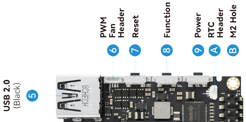
| 5 | USB-A | USB 2.0, black colour |
| 6 | Fan Header | 4-wire fan header utilising pulse width modulation |
| 7 | Reset Button | Force reboot your Edge-V |
| 8 | Function Button | Press this 3 times in 2 seconds to enter MaskROM mode |
| 9 | Power Button | This button turns on your Edge-V |
| A | RTC Battery Header | Header for attaching a battery for the real time clock |
| B | M2 Hole | M2 clearance holes for a case, or adding a heatsink |
| C | 40-Pin GPIO | access GPIO, or use it to add a Toneboard |
| D | Gesture Sensor | Control your Edge-V with a hand-wave |
| E | Infrared Module | 2-channel infrared receiver for use with Khadas IR remote |
| F | LEDs | Status indicator LEDs |
| G | I-Pex Wi-Fi / Bluetooth Connector | Wi-Fi / BT Antenna connector |
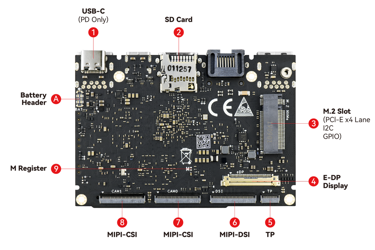
Back Side
| Component | Purpose | |
|---|---|---|
| 1 | USB-C | USB-C port that accepts 5-20V power input (PD only) |
| 2 | Micro-SD Card Slot | Boot alternative OSes via a Micro-SD card, or just for extra storage |
| 3 | M.2 Socket (PCI-E 2.1) | Connect 2280 NVMe SSDS at 4-lane speed with M2X Extension |
| 4 | E-DP Display | For connecting to external displays via E-DP |
| 5 | Touch Panel | For accepting touch-input |
| 6 | MIPI-DSI | MIPI-DSI header for connecting LCD screens |
| 7 | MIPI-CSI | For connecting to MIPI-CSI cameras |
| 8 | MIPI-CSI | For connecting to MIPI-CSI cameras |
| 9 | M-Register | Another way for entering upgrade mode |
| A | Li-Po Battery Connector | Connect a Lithium Polymer battery with the Juice Board |
Hardware buttons
| Reset | Function | Power | Purpose |
|---|---|---|---|
| x | Force Reboot Edge-V | ||
| x | Enter Upgrade Mode (TST) | ||
| x | Power On/Wake Up Edge-V | ||
| x | x | Enter Upgrade Mode (KEY) |
GPIO header pinout
| SIGNAL | PIN | PIN | SIGNAL |
|---|---|---|---|
| 5V | 1 | 21 | GND |
| 5V | 2 | 22 | SPI3_RXD/I2C0_SCK/GPIO1_C0 |
| HOST1_DM | 3 | 23 | SPI3_TXD/I2C0_SDA/GPIO1_B7 |
| HOST1_DP | 4 | 24 | GND |
| GND | 5 | 25 | I2C2_SCL/GPIO2_A1 |
| MCU_TX | 6 | 26 | I2C2_SDA/GPIO2_A0 |
| MCU_NRST | 7 | 27 | 3.3V |
| MCU_SWIM | 8 | 28 | GND |
| GND | 9 | 29 | I2S0_SCLK/GPIO3_D0 |
| ADC_IN2 | 10 | 30 | I2S_CLK/GPIO4_A0 |
| 1.8V | 11 | 31 | I2S0_SDO0/GPIO3_D7 |
| ADC_IN3 | 12 | 32 | 2S0_LRCK_TX/GPIO3_D2 |
| SPDIF/GPIO3_C0 | 13 | 33 | I2S0_SDI0/GPIO3_D3 |
| GND | 14 | 34 | GND |
| SPI3_CS/GPIO1_C2 | 15 | 35 | I2S0_SDI3SDO1/GPIO3_D6 |
| SPI3_CLK/GPIO1_C1 | 16 | 36 | 2S0_SDI2SDO2/GPIO3_D5 |
| GND | 17 | 37 | I2S0_SDI1SDO3/GPIO3_D4 |
| Linux_RX | 18 | 38 | I2S0_LRCK_RX/GPIO3_D1 |
| Linux_TX | 19 | 39 | MCU_PA1 |
| 3.3V | 20 | 40 | GND |
</tabbox>
Last modified: 2023/03/22 04:03 by nick


