Table of Contents
VIM3/3L Hardware Documentation
VIM3/3L Interfaces
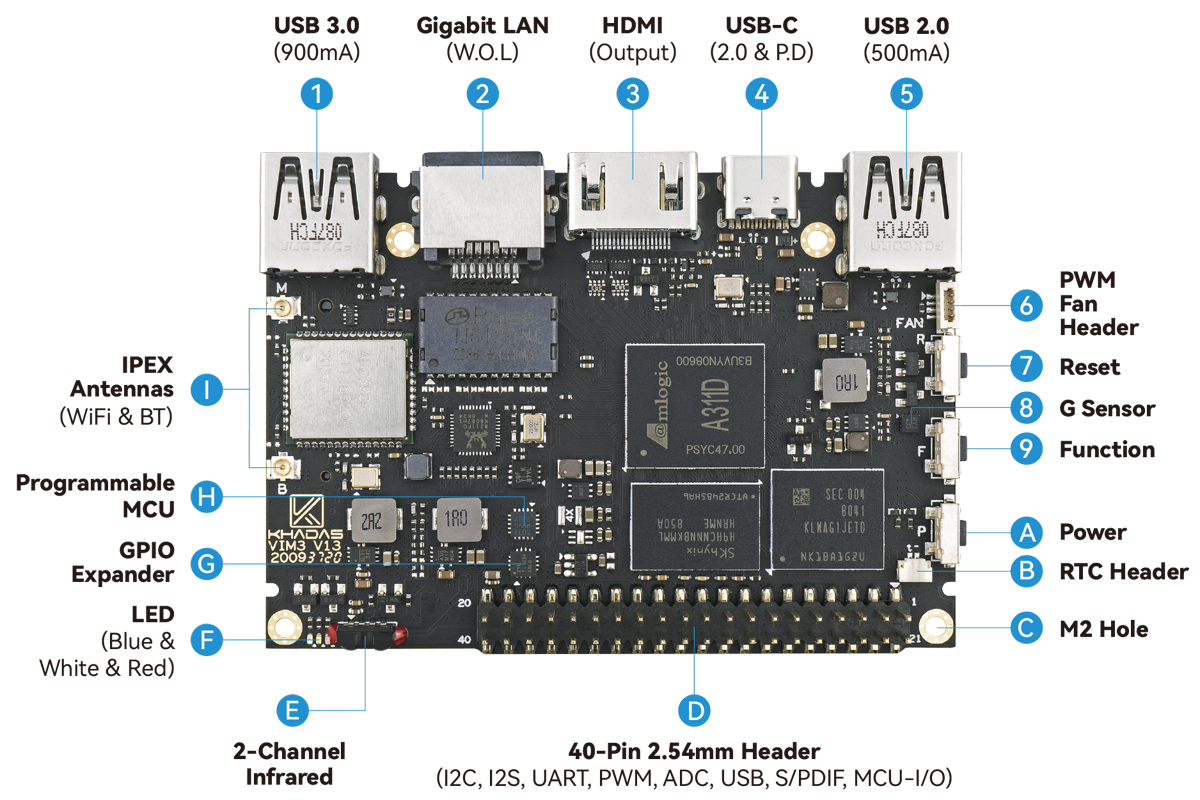
Top Side
| Component | Purpose | |
|---|---|---|
| 1 | USB-A | USB 3.0 port that swaps to 2.0 when PCI-E is active, 900mA output |
| 2 | RJ-45 | Gigabit LAN port that supports Wake-On-LAN |
| 3 | HDMI | HDMI port supporting CEC |
| 4 | USB-C | USB-C port with USB power delivery (5-20Vinput) and 2.0 speeds, can be used for upgrading the OS |
| 5 | USB-A | USB 2.0 port that supports 500mA output |
| 6 | Fan Header | 4-wire fan header utilising pulse width modulation |
| 7 | Reset Button | Force reboot your VIM3 |
| 8 | G-Sensor | 3-axis accelerometer |
| 9 | Function Button | Press this 3 times in 2 seconds to enter MaskROM mode |
| A | Power Button | This button turns on your VIM3 |
| B | RTC Header | A header for connecting a real-time clock (button) battery |
| C | M2 Hole | M2 clearance holes for a case, or adding a heatsink |
| D | 40-Pin GPIO | General input/output pins for VIM3's SoC, or plugging-in a Toneboard |
| E | Infrared Module | 2-channel infrared receiver for the Khadas IR remote |
| F | LEDs | Indicator LEDs |
| G | GPIO Expander | Increases VIM3's available I/O beyond what A311D can provide |
| H | MCU | STM8S003 micro-controller with programmable EEPROM |
| I | IPEX Antenna | Wi-Fi and Bluetooth antenna connector |
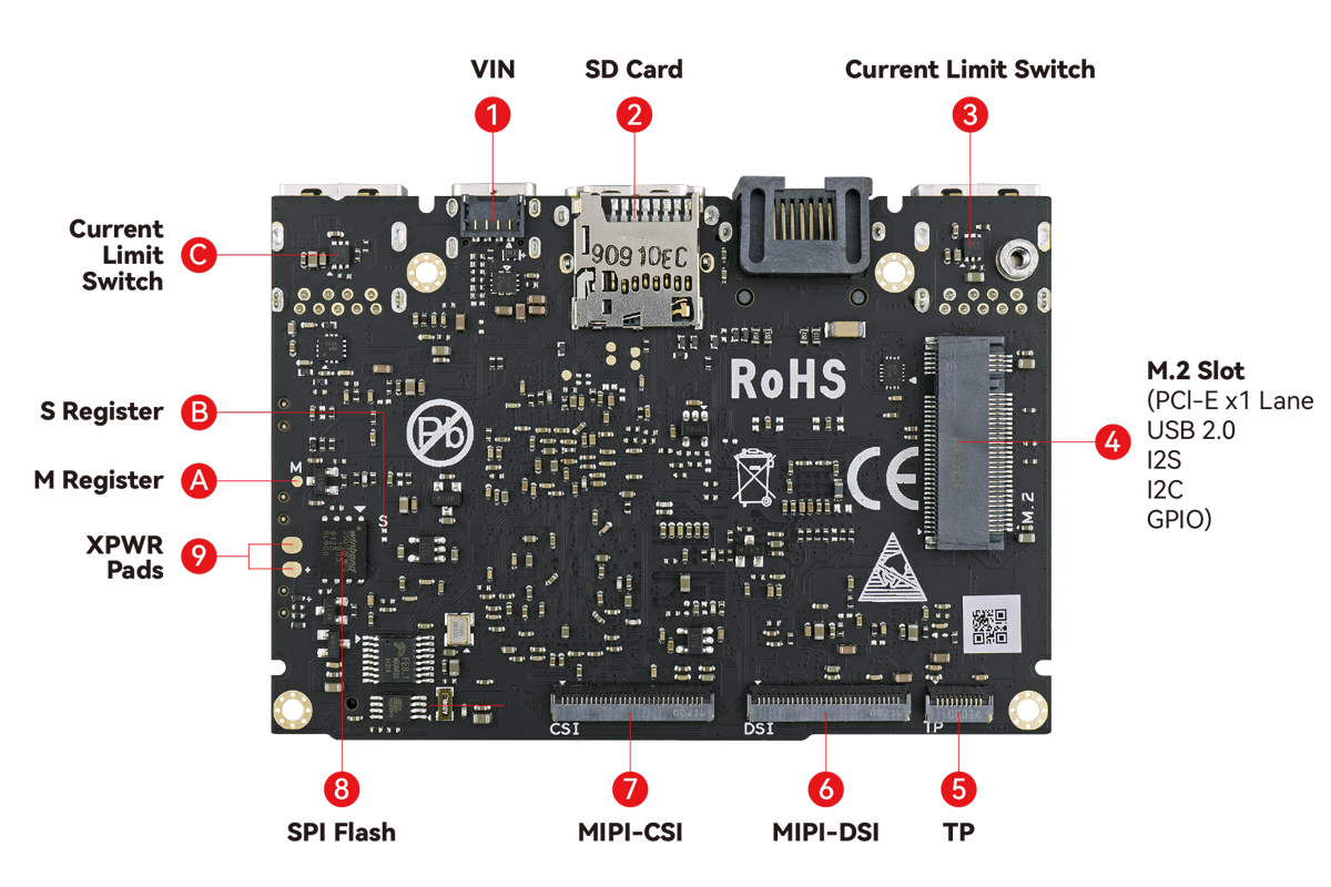
Back Side
| Component | Purpose | |
|---|---|---|
| 1 | VIN | 5-12V power input, supports Power-Over-Ethernet via M2X Extension |
| 2 | Micro-SD Slot | Molex Slot, spec version 2.x/3.x/4.x (SDSC/SDHC/SDXC) |
| 3 | Current Limit Switch | Prevents damage to VIM3 due to faulty loading conditions |
| 4 | M.2 Slot | PCIe 2.0 (x1 lane), supports M.2 2280 NVMe SSDs |
| 5 | TP | 10-pin 0.5mm pitch FPC connector for touch input |
| 6 | MIPI-DSI | 30-pin, 0.5mm pitch FPC connector for 4-lane 1080P displays |
| 7 | MIPI-CSI | 30-pin, 0.5mm pitch, 4-lane, dual cameras, 8MP image signal processing |
| 8 | SPI Flash | Flash memory module that interfaces over SPI |
| 9 | XPWR Pads | Connect an external power switch using these pads |
| A | M-Register | Shortcut to mask the eMMC |
| B | S-Register | Shortcut to mask the SPI Flash |
| C | Current Limit Switch | Prevents damage to VIM3 due to faulty loading conditions |
Hardware buttons
| Reset | Function | Power | Purpose |
|---|---|---|---|
| x | Force Reboot VIM3 | ||
| x | Enter Upgrade Mode (TST) | ||
| x | Power ON/Wake Up VIM3 | ||
| x | x | Enter Upgrade Mode (KEY) |
GPIO header pinout
| SIGNAL | PIN | PIN | SIGNAL |
|---|---|---|---|
| 5V | 1 | 21 | GND |
| 5V | 2 | 22 | I2C_M3_SCL |
| USB_DM | 3 | 23 | I2C_M3_SDA |
| USB_DP | 4 | 24 | GND |
| GND | 5 | 25 | I2C_AO_SCK |
| VCC_MCU | 6 | 26 | I2C_AO_SDA |
| MCU_NRST | 7 | 27 | 3.3V |
| MCU_SWIM | 8 | 28 | GND |
| GND | 9 | 29 | I2SB_SCLK |
| ADC_CH0 | 10 | 30 | I2S_MCLK0 |
| 1.8V | 11 | 31 | I2SB_SDO |
| ADC_CH3 | 12 | 32 | I2SB_LRCK |
| SPDIF_OUT | 13 | 33 | I2SB_SDI |
| GND | 14 | 34 | GND |
| UARTC_RX | 15 | 35 | PWM_F |
| UARTC_TX | 16 | 36 | RTC_CLK |
| GND | 17 | 37 | GPIOH_4 |
| Linux_RX | 18 | 38 | MCU_PA1 |
| Linux_TX | 19 | 39 | GPIODZ_15 |
| 3.3V | 20 | 40 | GND |


